1. Inngangur
Welcome to the instruction manual for your DAOKI C51 4-Bit Digital LED Electronic Clock DIY Kit. This kit provides all the necessary components to assemble a functional digital clock, offering an engaging and educational experience in electronics assembly.
1.1 Fyrirhuguð notkun
This kit is designed for hobbyists, students, and anyone interested in learning about basic electronics and soldering. The assembled clock features a 4-digit LED display, timekeeping, and alarm functions. It is intended for indoor use as a desktop or workbench clock.
2. Öryggisupplýsingar
Please read and understand all safety instructions before beginning assembly. Failure to follow these guidelines may result in injury or damage to the product.
- Soldering Safety: Always use a soldering iron in a well-ventilated area. Wear appropriate eye protection to shield against solder splashes. Avoid touching the hot tip of the soldering iron.
- Rafmagnsöryggi: Ensure the power supply used is within the specified voltage range (3V-6V DC). Do not connect the kit to AC power directly. Disconnect power before making any adjustments or repairs.
- Meðhöndlun íhluta: Some electronic components can be sensitive to static electricity. Handle components by their edges and avoid touching pins directly.
- Litlir hlutar: This kit contains small parts that could be a choking hazard. Keep out of reach of small children.
3. Innihald pakka
Verify that all components listed below are present in your kit before starting assembly. Refer to the image below for a visual representation of the kit's contents.
- Printed Circuit Board (PCB)
- AT89C2051 Microcontroller (pre-programmed)
- IC fals (DIP-20)
- 0.56 inch 4-digit Red Digital LED Display
- Viðnám (misvísandi gildi)
- Capacitors (electrolytic and ceramic)
- Díóða
- Smári
- Kristallsveifla (12MHz)
- Push Buttons (2)
- Buzzer
- DC Power Jack / Terminal Block
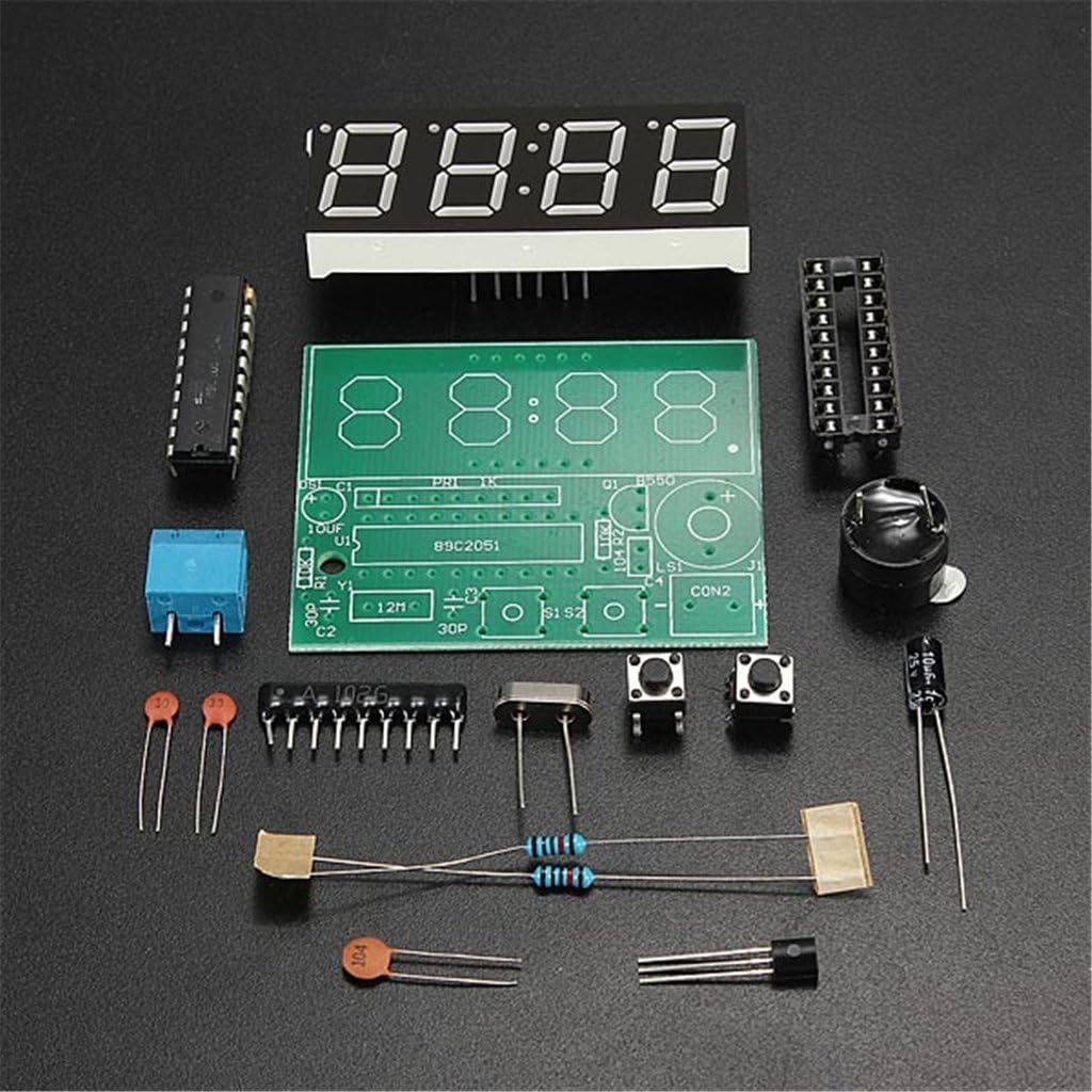
Image 3.1: All components of the DAOKI C51 Digital LED Electronic Clock DIY Kit, including the PCB, microcontroller, LED display, resistors, capacitors, diodes, transistors, crystal, buttons, and buzzer.
4. Uppsetning og samsetning
This section guides you through the assembly process. It is recommended to solder components in order of height, starting with the lowest profile components first.
4.1 Auðkenning íhluta
Before soldering, identify each component by comparing it to the provided schematic and component list. Resistors are identified by color bands, capacitors by their values printed on them, and diodes/transistors by their markings and shape.
4.2 Soldering Steps
- Viðnám: Solder all resistors (R1-R6) into their designated positions on the PCB. Ensure they are flush with the board.
- Díóða: Solder the diodes (D1-D2). Pay close attention to the polarity; the band on the diode must match the band marking on the PCB.
- Þéttar: Solder the ceramic capacitors (C2, C3, C5) and then the electrolytic capacitors (C1, C4). For electrolytic capacitors, ensure the longer lead (positive) matches the '+' marking on the PCB, or the stripe on the capacitor matches the negative marking.
- Smári: Solder the transistor (Q1) into its position, matching its flat side with the outline on the PCB.
- Crystal Oscillator: Solder the 12MHz crystal oscillator (Y1). This component is not polarized.
- Þrýstihnappar: Solder the two push buttons (S1, S2).
- IC tengi: Solder the 20-pin IC socket (U1). Ensure the notch on the socket aligns with the notch marking on the PCB. After soldering, carefully insert the AT89C2051 microcontroller into the socket, ensuring all pins align correctly and are not bent.
- Suð: Solder the buzzer (U2). Pay attention to polarity if indicated on the buzzer or PCB.
- Stafrænn skjár: Solder the 4-digit LED display (DS1) onto the PCB. Ensure it is oriented correctly so the digits face the desired direction.
- Máttur tengi: Solder the DC power jack or terminal block (CON2) for power input.

Image 4.1: The fully assembled DAOKI C51 Digital LED Electronic Clock circuit board, showing all components soldered into place and the LED display mounted.
4.3 Skýringarmynd
The following image provides the circuit schematic for the DAOKI C51 Digital LED Electronic Clock, useful for understanding component connections and troubleshooting.

Image 4.2: Circuit schematic diagram detailing the connections between the AT89C2051 microcontroller, LED display, power supply, and other components of the clock kit.
5. Notkunarleiðbeiningar
Once assembled, connect a 3V to 6V DC power supply to the designated power input. The clock should power on and display the current time or a default value.
5.1 Grunnvirkni hnappa
- Button S1: Venjulega notað til að velja stillingu eða auka gildi.
- Button S2: Typically used for entering a setting mode or confirming a selection.
5.2 Stilla tíma
- Press and hold S2 until the hour digits begin to flash. This indicates you are in time setting mode.
- Use S1 to adjust the hour. Each press will increment the hour.
- Press S2 again to move to the minute setting. The minute digits will flash.
- Use S1 to adjust the minutes.
- Press S2 a third time to save the time and exit the setting mode.
5.3 Viðvörunarstillingar
The clock supports two alarm settings. The exact method for setting and enabling alarms may vary slightly based on the firmware, but generally follows these steps:
- From the normal time display, short press S2 to cycle through display modes (e.g., Time -> Alarm 1 -> Alarm 2).
- When 'Alarm 1' (or 'A1') is displayed, press and hold S2 to enter Alarm 1 setting mode.
- Use S1 to set the desired alarm hour, then press S2 to move to minutes.
- Use S1 to set the desired alarm minutes, then press S2 to save.
- To enable/disable the alarm, a short press of S1 while in the alarm display mode might toggle it on/off (indicated by a small dot or 'ON'/'OFF' on the display).
- Repeat for Alarm 2 if desired.
5.4 Hóurly Klukka
The clock features an hourly chime function, typically active between 8 AM and 8 PM (20:00). To enable or disable this feature, you may need to enter a specific setting mode, often by pressing and holding both S1 and S2 simultaneously, or by cycling through modes with S2 until a chime setting appears, then using S1 to toggle.
6. Viðhald
6.1 Þrif
To clean the clock, gently wipe the display and PCB with a soft, dry cloth. Avoid using liquid cleaners or abrasive materials, as these can damage the components or display.
6.2 aflgjafi
Always use a stable DC power supply within the 3V to 6V range. Using an incorrect voltage or an unstable power source can lead to erratic behavior or permanent damage to the circuit.
7. Bilanagreining
If you encounter issues with your assembled clock, refer to the following common problems and solutions:
- Klukkan kveikir ekki á sér:
- Athugið tengingar við aflgjafa og gætið þess að hljóðstyrkurinn sé rétturtage (3V-6V jafnstraumur).
- Inspect all solder joints for cold joints, bridges, or unsoldered pins.
- Verify the AT89C2051 microcontroller is correctly seated in its socket and oriented properly.
- Ensure diodes (D1, D2) are soldered with correct polarity.
- Incorrect or Partial Display:
- Check solder joints for the 4-digit LED display.
- Inspect for any solder bridges between display pins or PCB traces.
- Verify the display is inserted correctly.
- Hnappar svara ekki:
- Check solder joints for both push buttons (S1, S2).
- Ensure no debris is preventing button presses.
- Tímaónákvæmni:
- Verify the crystal oscillator (Y1) is correctly soldered.
- Ensure the associated capacitors (C2, C3) are correctly installed.
8. Tæknilýsing
| Eiginleiki | Forskrift |
|---|---|
| Master Chip | AT89C2051 |
| Framboð Voltage | 3V ~ 6V DC |
| Stærð PCB | 52 x 42 mm (2.05"W x 1.65"H) |
| Skjár Tegund | 0.56 inch Red Digital LED |
| Tíma nákvæmni | Error range -1 to +1 seconds every 24 hours |
| Sérstakir eiginleikar | Seconds correction, Two alarm settings, Hourly chime (8-20 o'clock) |
| Tegundarnúmer vöru | BG-US-920198 |
9. Ábyrgð og stuðningur
9.1 Upplýsingar um ábyrgð
As a DIY kit, the warranty typically covers manufacturing defects of individual components at the time of purchase. Damage resulting from incorrect assembly, improper soldering, or use outside of specified parameters is not covered. Please inspect all components upon receipt.
9.2 Þjónustuver
For technical assistance or inquiries regarding missing/defective components, please contact your seller or the DAOKI customer support channel through which you purchased the product. Provide your order details and a clear description of the issue for efficient support.