1. Inngangur
This manual provides detailed instructions for the installation, configuration, operation, and maintenance of the Logicbus Z109REG2-H Universal Converter. The Z109REG2-H is designed to manage and convert various analog input signals (mA, V, PT100, Pt1000, Pt500, Ni100, TCs, Ohm) into standard mA/V output signals, ensuring reliable data integrity through 3-way galvanic isolation.
2. Öryggisupplýsingar
Please read and understand all safety instructions before installing or operating the device. Failure to follow these instructions may result in equipment damage, personal injury, or death.
- Uppsetning og viðhald ætti aðeins að vera framkvæmt af hæfu starfsfólki.
- Gangið úr skugga um að rafmagnið sé aftengt áður en rafmagnstengingar eru gerðar.
- Verify correct wiring according to the connection diagrams to prevent damage.
- Do not operate the device in environments exceeding its specified operating conditions.
- Verndaðu tækið gegn raka, ryki og miklum hita.
3. Vöru lokiðview
The Z109REG2-H is a compact, DIN-rail mountable universal converter. It features clearly labeled terminal blocks for inputs, outputs, and power, along with status indicators on the front panel.
3.1. Front Panel and Connections
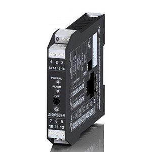
Mynd 1: Framan view of the Logicbus Z109REG2-H Universal Converter. This image displays the device's compact black housing, designed for DIN rail mounting. Visible on the front are two sets of screw terminals, labeled 1-3 and 13-16 at the top, and 7-9 and 10-12 at the bottom. Between these terminals, three LED indicators are present: 'PWR/TAL' (Power/Talk), 'ALARM', and 'COM' (Communication). The model number 'Z109REG-H' is also clearly printed on the lower half of the device's front face.
Framhliðin inniheldur:
- Terminal blokkir: Numbered 1-3, 13-16 (top) and 7-9, 10-12 (bottom) for various input, output, and power connections.
- PWR/TAL LED: Indicates power status and communication activity.
- ALARM LED: Kviknar þegar viðvörunarástand greinist.
- COM LED: Indicates communication status.
- Gerðarnúmer: Z109REG-H, identifying the device.
4. Uppsetning
4.1. Uppsetning
The Z109REG2-H is designed for DIN rail mounting. Securely attach the device to a standard DIN rail in a suitable enclosure, ensuring adequate ventilation and clearance for wiring.
4.2. Raflagnir
Refer to the specific wiring diagrams provided with your product documentation for detailed connection instructions. General wiring principles are as follows:
- Aflgjafi: Connect the 85-265 V AC/DC power supply to the designated terminals. Ensure the power source matches the device's requirements.
- Inntaksmerki: Connect your analog sensor (e.g., current, voltage, thermocouple, RTD, potentiometer) to the universal input terminals. The device supports 2-wire sensor powering (20 Vdc stabilized, 20mA max with short-circuit protection).
- Úttaksmerki: Connect the standard mA/V output signals to your receiving device (e.g., PLC, DCS).
- Digital Contact: The relay (SPST) output can be configured as an ALARM or STROBE contact. Connect as required for your application.
4.3. Stillingar
The Z109REG2-H offers multiple configuration methods:
- DIP-rofar: Basic configuration for input type, START-END scale, output mode (zero elevation, scale inversion), and output voltage type (mA or V) can be set using the internal DIP-switches. Consult the product datasheet for switch settings.
- PC hugbúnaður: For advanced configuration, connect the device to a PC. The software allows programming of beginning and end scale, additional input types, square root extraction, filter settings, burn-out detection, and relay output parameters.
- Handheld Device: A compatible handheld device can also be used for field configuration.
5. Notkunarleiðbeiningar
Once properly installed and configured, the Z109REG2-H operates automatically.
- Kveikt á: Apply power to the device. The PWR/TAL LED should illuminate, indicating normal operation.
- Eftirlit: Observe the ALARM LED for any fault conditions or out-of-scale readings. The COM LED indicates communication activity during configuration or data exchange.
- STROBE Input: If configured, the STROBE input can be used to activate the analog output on a PLC command, providing multiplexing capabilities.
6. Viðhald
The Z109REG2-H is designed for minimal maintenance. Regular checks include:
- Þrif: Haldið tækinu hreinu og ryklausu. Notið mjúkan, þurran klút til að þrífa. Notið ekki slípiefni eða leysiefni.
- Tengingarheilindi: Athugið reglulega allar raflagnatengingar hvort þær séu þéttar eða merki um tæringu.
- Umhverfisskilyrði: Gakktu úr skugga um að rekstrarumhverfið sé innan tilgreindra hitastigs- og rakastigsmarka.
7. Bilanagreining
Ef tækið virkar ekki eins og búist var við skaltu íhuga eftirfarandi úrræðaleitarskref:
- No Power (PWR/TAL LED off): Verify the power supply connections and voltage. Check for blown fuses in the power circuit.
- Incorrect Output Reading:
- Check input sensor wiring and functionality.
- Verify DIP-switch settings for input type and scale.
- Confirm PC software configuration parameters (scale, filter, burn-out).
- Ensure the output receiving device is correctly configured and calibrated.
- ALARM LED On: This indicates an out-of-scale condition or a setting error. Review input signal range and configuration settings.
- Communication Issues (COM LED): Ensure correct communication cable connection and PC software settings.
Ef vandamálin halda áfram skaltu hafa samband við tæknilega aðstoð.
8. Tæknilýsing
| Eiginleiki | Forskrift |
|---|---|
| Fyrirmynd | Z109REG2-H |
| Inntakstegundir | Voltage, Current, Thermocouples, Thermoresistances (PT100, Pt1000, Pt500, Ni100), Potentiometer, Rheostat |
| Úttakstegundir | Isolated Analog Output (Voltage og núverandi) |
| Aflgjafi | 85-265 V AC/DC |
| Sensor Power (2-wire) | 20 Vdc stabilized, 20mA max with short-circuit protection |
| Stillingar | DIP-switches, PC software, Handheld device |
| Galvanísk einangrun | 3-way (Power supply // Input // Output) |
| Insulation (Supply to Output/Input) | 3750 Vac |
| Insulation (Output to Input) | 1500 Vac |
| Digital Contact | Relay (SPST), programmable as ALARM or STROBE |
| Mál | 5 x 1 x 4 tommur (u.þ.b. 127 x 25.4 x 101.6 mm) |
| Þyngd | 7.05 aura (u.þ.b. 200 grömm) |
| Framleiðandi | Seneca |
9. Upplýsingar um ábyrgð
Warranty terms and conditions for the Logicbus Z109REG2-H Universal Converter are provided by the manufacturer, Seneca, or your authorized reseller. Please refer to the documentation included with your purchase or contact your supplier for specific warranty details and duration.
10. Tæknileg aðstoð
For technical assistance, troubleshooting beyond the scope of this manual, or inquiries regarding product functionality, please contact your Logicbus supplier or the manufacturer, Seneca. Have your product model number (Z109REG2-H) and any relevant error messages or symptoms ready when contacting support.


