1. Vöru lokiðview
The DROK DC Adjustable Buck Converter is a versatile step-down voltagE-stýring hönnuð til að umbreyta hærri jafnstraumsinntaksrúmmálitage á lægri, stillanlegan jafnstraumsútgangsstyrktage. This module features a large LCD screen for simultaneous display of voltage and current, a USB output port, and comes with a protective acrylic case for enhanced durability. It is suitable for various applications including power supply, battery charging, and LED driving.
- Inntak Voltage Svið: 6V-32V
- Output Voltage Svið: 1.25V-32V (Input must be at least 1.5V higher than output)
- Hámarksúttaksstraumur: 5A (recommended within 4.5A)
- Hámarks úttaksstyrkur: 75W (recommended within 50W)
- Skjár: LCD screen showing voltage og núverandi
- Eiginleikar: Stöðugt voltage and current modes, voltage and current calibration, USB output port.
2. Auðkenning íhluta
Familiarize yourself with the key components and indicators of the buck converter module.

Mynd 2.1: Framan View með merktum íhlutum
This image displays the front of the DROK DC Adjustable Buck Converter, highlighting key features such as the LCD Voltage Current Dual Display, USB Indicator, Input/Output terminals, Setting & Mode buttons, and adjustment potentiometers for Voltage and Current Regulation. It also shows indicators for Constant Current, Charging, and Full Charged status.

Mynd 2.2: Aftan View with Internal Components
This image shows the rear side of the buck converter, revealing internal components such as the Power Supply Chip (where a cooling fan can be attached), the main inductor, Large Current Schottky diode, Single Chip Microcomputer, and the USB Output port. Input and Output terminals are also visible.
3. Protective Case Assembly
The buck converter comes with a protective acrylic case that requires simple assembly. The case protects the module from accidental contact and provides a stable mounting platform.
3.1. Samsetningarskref
- Carefully remove all acrylic panels and screws from the packaging.
- Place the buck converter module onto the bottom acrylic panel, aligning the mounting holes.
- Secure the module to the bottom panel using the provided copper cylinder screws (M3*6) and roundhead screws (M3*6).
- Attach the four double-pass screws (M3*12) to the corners of the bottom panel, which will serve as standoffs for the top panel.
- Place the top acrylic panel onto the double-pass screws, aligning the holes.
- Secure the top panel using the remaining roundhead screws (M3*6).
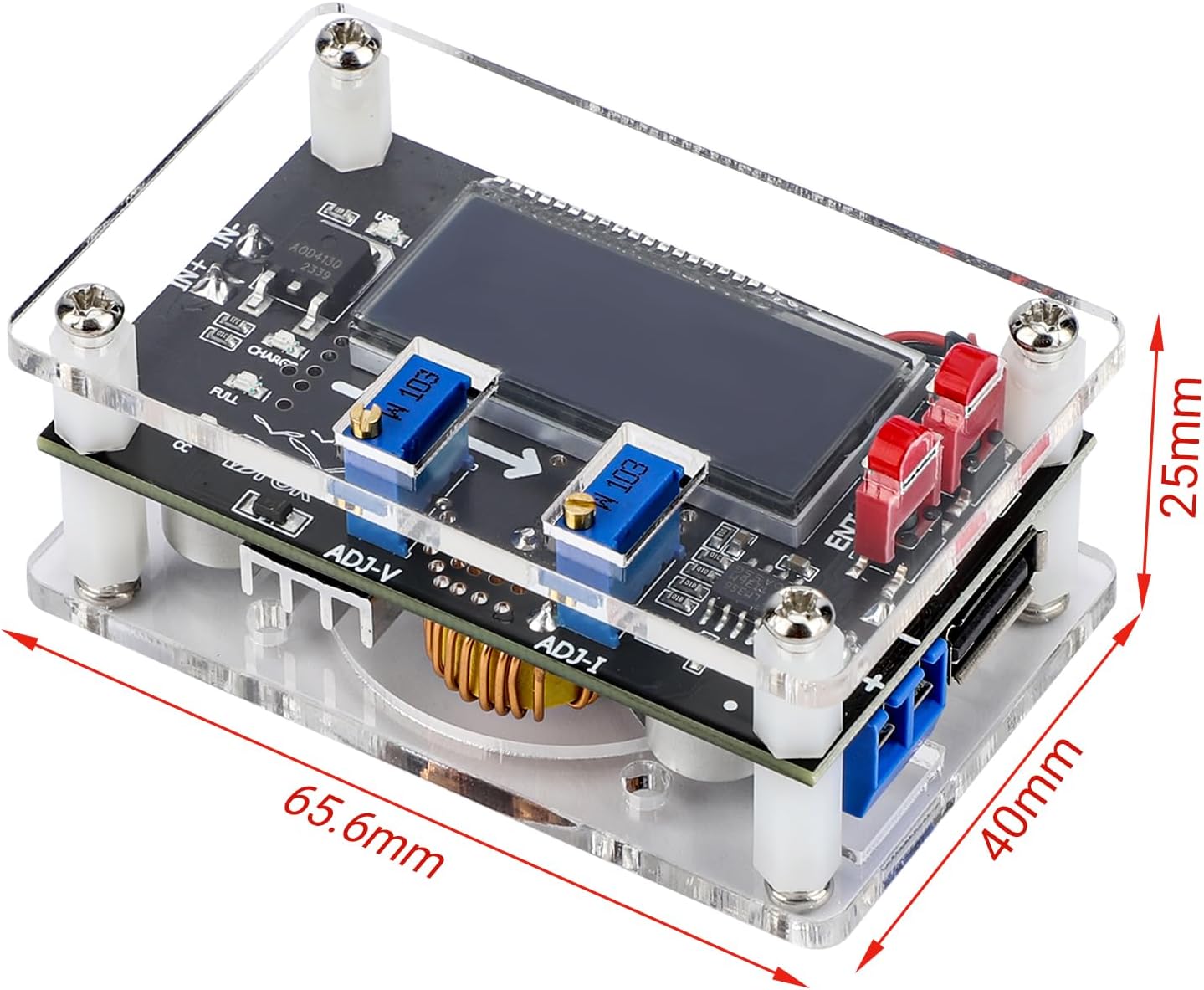
Figure 3.1: Assembled Module with Dimensions
This image shows the DROK buck converter fully assembled within its clear acrylic protective case, with dimensions of 65.6mm (length), 40mm (width), and 25mm (height) indicated.
4. Tæknilýsing
Detailed technical specifications for the DROK DC Adjustable Buck Converter.
| Parameter | Gildi |
|---|---|
| Inntak Voltage | 6V-32V |
| Output Voltage | 1.25V-32V (Input must be 1.5V higher than output) |
| Úttaksstraumur | Max. 5A (recommend within 4.5A) |
| Output Power | Max. 75W (recommend within 50W) |
| Rekstrarhitastig | -20°C til +70°C |
| Rekstrartíðni | 180KHz |
| Skilvirkni viðskipta | Allt að 96% |
| Skammhlaupsvörn | Já |
| Vernd innsláttar pólunar | Engin |
| Ofhitavörn | Yes (Automatic shutdown) |
| Tengingaraðferð | Terminals or solder pads |
| Mál einingar | 65.6 x 40 x 25 mm |
| Gerðarnúmer | F-MP2304 |
5. Notkunarleiðbeiningar
5.1. Grunntenging
- Connect your DC input power source to the VIN+ og VIN- terminals. Ensure correct polarity as there is no input reverse polarity protection.
- Connect your load to the VOUT+ og VOUT- skautanna.
- Power on the input source. The LCD will display the current input and output voltage/núverandi.
5.2. Binditage Aðlögun
Til að stilla úttak voltage:
- Finndu ADJ-V potentiometer (usually labeled 'V' or 'Voltage Regulation').
- Turn the potentiometer clockwise to increase the output voltage.
- Turn the potentiometer counter-clockwise to decrease the output voltage.
- Monitor the LCD display for the desired output voltage.
5.3. Current Adjustment (Constant Current Mode)
The module can operate in constant current mode, useful for battery charging or driving LEDs. Current adjustment is effective only when the output voltage er yfir 2V.
- Finndu ADJ-I potentiometer (usually labeled 'I' or 'Current Regulation').
- To set the constant current limit, short the output terminals (VOUT+ and VOUT-) with an ammeter or a suitable load.
- Snúðu á ADJ-I potentiometer clockwise to increase the current limit.
- Snúðu á ADJ-I potentiometer counter-clockwise to decrease the current limit.
- Once the desired current limit is set, remove the short circuit or connect your actual load. The module will limit the current to the set value if the load attempts to draw more.
5.4. Binditage Calibration Method
Ef birt voltage is inaccurate, follow these steps to calibrate:
- Ensure the module is powered off.
- Ýttu á og haltu inni "SETT" key, then power on the module. The LCD screen will start to flash, indicating entry into voltage kvörðunarhamur.
- Slepptu "SETT" lykill.
- Notaðu "SETT" og "ENT" takkar til að stilla birtan hljóðstyrktage til að passa við raunverulegt inntaksmagntage measured with a precise multimeter.
- The calibration will automatically save after 2 seconds of inactivity. Power off the module to complete the calibration.
5.5. Current Calibration Method
This method is suitable for no-load current display or slightly large current applications.
- Ensure the module is powered off.
- Ýttu á og haltu inni "ENT" key, then power on the module. The LCD screen will start to flash, indicating entry into current calibration mode.
- Slepptu "ENT" lykill.
- Notaðu "SETT" og "ENT" keys to adjust the displayed current to match the actual current measured with a precise ammeter.
- The calibration will automatically save after 2 seconds of inactivity. Power off the module to complete the calibration.
5.6. Notkun USB-tengis
The integrated USB port provides an output voltage identical to the main output terminals (VOUT). It is important to note:
- Voltage Samsvörun: If the main output is set to 10V, the USB port will also output 10V, not the standard 5V. Always verify the output voltage before connecting standard USB devices to prevent damage.
- Power Cycle Behavior: The USB port does not remain enabled during a power off/on sequence. While the converter remembers the voltage setting, the USB port will disable and must be manually re-enabled after each power cycle.
6. Viðhald
To ensure optimal performance and longevity of your DROK Buck Converter:
- Hitaleiðni: When operating at currents higher than 3A or power exceeding 35W, it is crucial to enhance heat dissipation. Consider attaching a cooling fan to the designated area on the power supply chip (refer to Figure 2.2) or using a heatsink.
- Hreinlæti: Keep the module free from dust and debris. Use a soft, dry brush or compressed air for cleaning.
- Umhverfisskilyrði: Operate the module within the specified temperature range (-20°C to +70°C) and avoid high humidity environments.
- Tengingar: Periodically check all input and output connections to ensure they are secure and free from corrosion.
7. Troubleshooting and Safety Precautions
7.1. Mikilvægar varúðarráðstafanir
- Rétt árgtage Stilling: Always verify the output voltage setting before connecting any device to the converter. Incorrect voltage can damage your equipment.
- USB tengi Voltage: Be aware that the USB port output voltage matches the main output voltage. It is NOT fixed at 5V. Connecting 5V-only devices when the output is higher than 5V will cause damage.
- No Input Reverse Polarity Protection: Ensure input power is connected with correct polarity (VIN+ to positive, VIN- to negative). Reverse connection will damage the module.
- Inntak Voltage Krafa: Inntak binditage must always be at least 1.5V higher than the desired output voltage for proper buck conversion.
- Hitastjórnun: Operating at high power (over 35W) or high current (over 3A) without adequate heat dissipation can lead to overheating and automatic shutdown due to over-temperature protection. Ensure proper cooling.
- Skammhlaupsvörn: The module includes short circuit protection, but prolonged short circuits should be avoided.
7.2. Algeng vandamál
- No Output Voltage: Check input power supply, ensure correct polarity, and verify that the input voltage is sufficient (at least 1.5V higher than the desired output).
- Ónákvæmar skjálestur: Flytja binditage and current calibration as described in Section 5.4 and 5.5.
- Ofhitnun einingarinnar: Reduce load or enhance heat dissipation by adding a heatsink or cooling fan, especially when operating at higher power/current levels.
- USB Port Not Working After Power Cycle: Manually re-enable the USB port after each power cycle, as it does not retain its enabled state.


